Raspberry Pi with Photoresistor
GitHub code: Reeflection/InteractionControl at main · 21020295/Reeflection
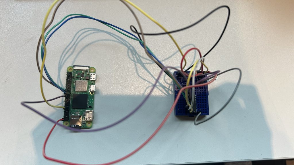
This week I worked on how to built a system where a Raspberry Pi Zero 2 W plays a video on an HDMI screen when a light sensor detects low light. No keyboard, no monitor, no manual start required.
Gathering Components
I picked a photoresistor (also called an LDR, or light-dependent resistor) for one key reason: simplicity.
A photoresistor changes its resistance based on the light it receives:
- Bright light → low resistance
- Low light → high resistance
Why this sensor?
- It’s inexpensive and widely available.
- It doesn’t require complex circuits or components.
- It perfectly fits the “is it light or dark?” question I wanted the Raspberry Pi to answer.
For my project, I only needed to detect when something covered the sensor (like a hand or an object), and the LDR was ideal.
The Raspberry Pi’s GPIO pins can only handle digital signals (high or low). But the photoresistor outputs an analog signal (a smooth voltage change depending on light).
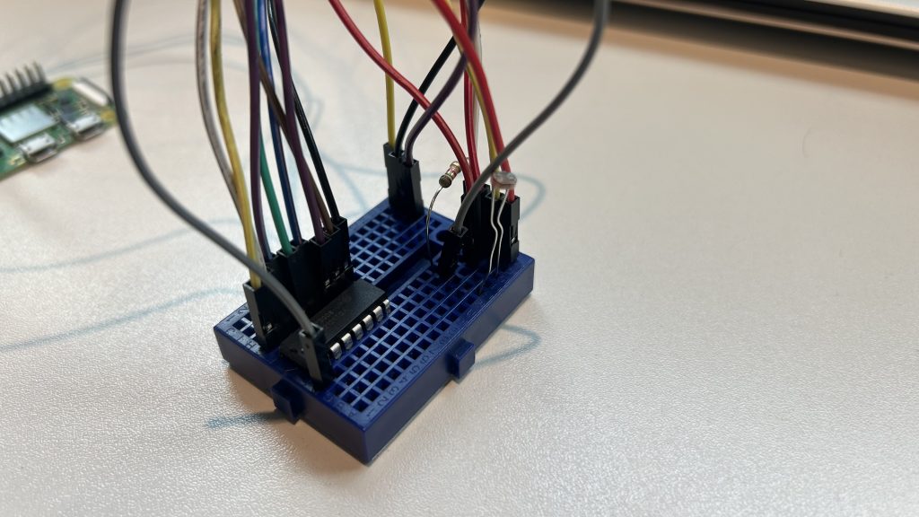
To bridge the gap, I added an MCP3008 analog-to-digital converter (ADC). This chip:
- Reads the varying voltage from the LDR + resistor voltage divider circuit.
- Converts it into a 10-bit digital value (0 to 1023).
- Sends it to the Raspberry Pi over SPI (Serial Peripheral Interface).
Without the ADC, the Pi couldn’t read the subtle changes in light intensity, only an on/off threshold.
Test Circut with LED
Before jumping into video playback, I wanted to make sure the electronics worked.
I wired up an LED and wrote a Python script:
If the light sensor reading was below a set threshold (i.e., low light), the LED turned on or blinked.
If the light was above the threshold, the LED stayed off.
This step was critical for:
– Confirming the LDR + MCP3008 circuit worked.
– Testing the Python SPI communication on the Pi.
– Making sure my threshold values were calibrated.
Once I saw the LED responding reliably to my hand covering and uncovering the sensor, the system was ready for the next stage.
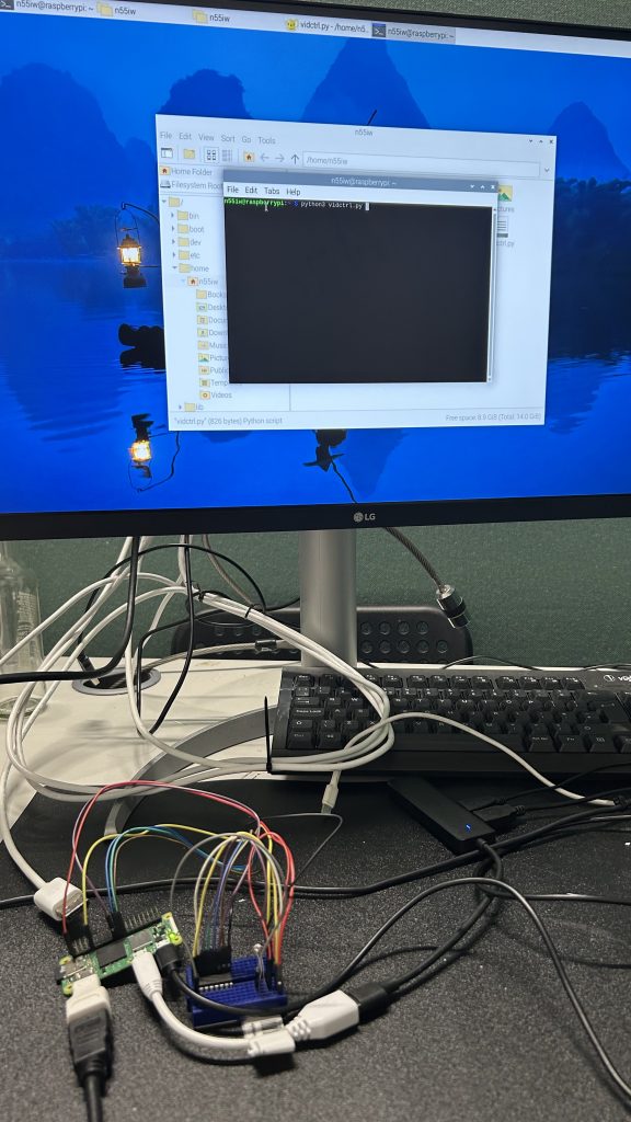
Working with Raspberry Pi
Next, I replaced the LED control with a system command to play a video.
In my Python script, I used:
subprocess.run(['cvlc', '--fullscreen', '--play-and-exit', '/home/n55iw/video.mp4'])Now, whenever the light sensor dropped below the threshold, the Raspberry Pi launched VLC and played the video on the HDMI screen.
I didn’t want to manually SSH in or start the script every time the Pi rebooted or swapped displays.
To fix this, I set up a systemd service:
- It runs the Python script automatically at boot.
- It keeps the script running in the background, even without a logged-in user.
- It restarts the script if it crashes.
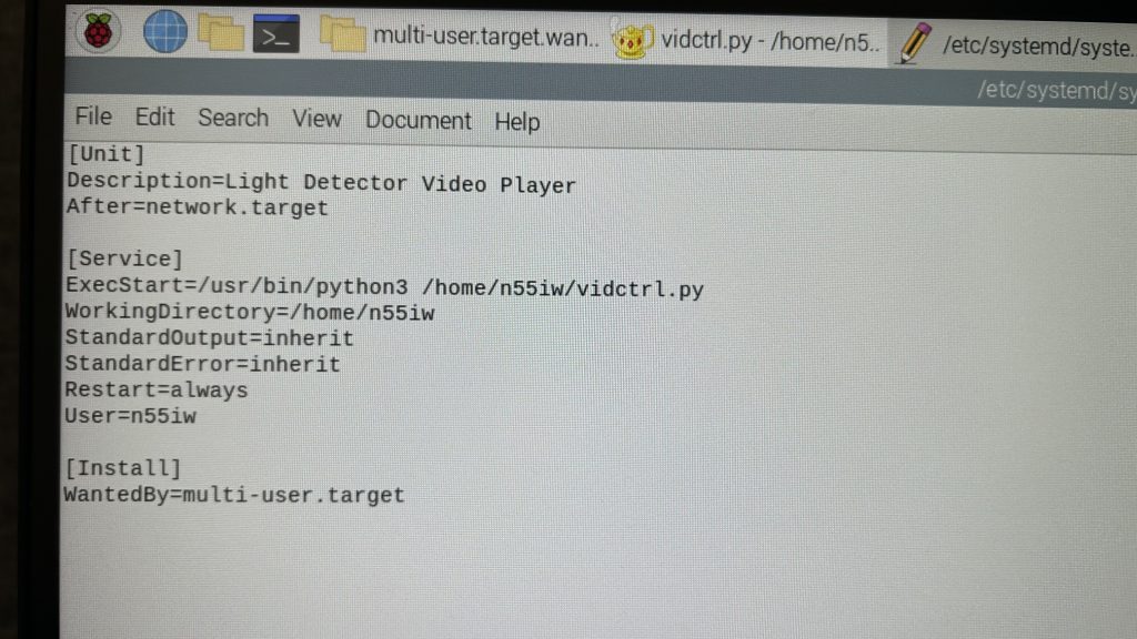
I saved this as /etc/systemd/system/lightdetector.service.
Then I ran:
sudo systemctl daemon-reload
sudo systemctl enable lightdetector.service
sudo systemctl start lightdetector.service
From that point on, the script ran automatically every time the Raspberry Pi booted, with no manual commands needed.
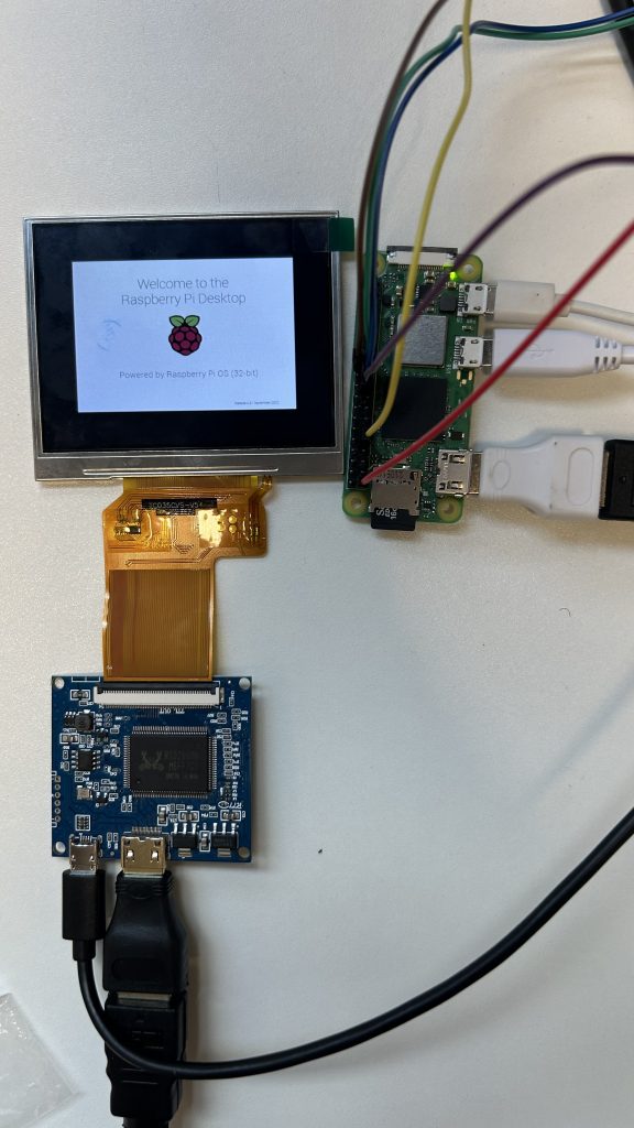
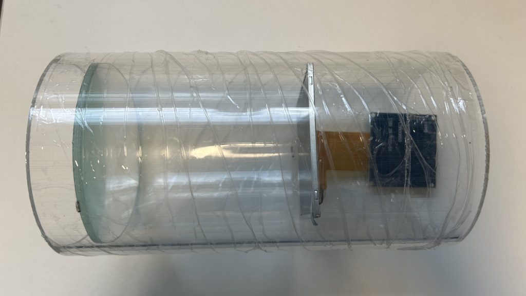
Placing the Screen and Magnifying Lens
To give the illusion of a larger display, I used a magnifying glass in front of the small round screen. But this setup required careful calculation.
First, I determined the magnification factor. I used a 3x magnifying lens, meaning the virtual image would appear 3 times as large. This magnifier has a specific focal length, calculated as:
P (Magnifying Power) = 1 + 25/f (Focal Length)
In my case the focal length is 12.5 cm.
To make sure the image appeared sharp and magnified:
I placed the screen just inside the lens’s focal length, so it produced a virtual, upright magnified image.
I positioned the viewer (eye) as close as possible to the magnifying lens to get the widest field of view.
I tested by adjusting the distances along the pipe:
Screen to lens: slightly more than the focal length (13cm)
Lens to eye: close to the eye, 2 cm.
This gave the audience the illusion that they were watching a much larger display, even though the physical screen was smaller.
These distance calculations were critical to avoid blurry or distorted images and to maximise the visual impact of the magnifier setup.
Reeflection
This week was full of technical hurdles but also small victories. Setting up the Raspberry was challenging at first, especially since I hadn’t used it before. But successfully getting the sensor to trigger the digital content was incredibly rewarding. It made me realise how much I enjoy the intersection of physical and digital experiences. While I hit plenty of frustrating obstacles, this week taught me patience, resilience, and the joy of finally making something work.